AS
All work

Project 02 · December 2025

Quadruped Walking Robot

From CAD to a robot that walks at 25.6 cm/s

This project takes a quadruped from initial concept through CAD design, physics simulation, fabrication and finally autonomous walking in the real world. The finished robot reached a maximum walking speed of 25.6 cm/s.

CADSimulationRoboticsEmbedded SystemsPythonPrototypingOOP
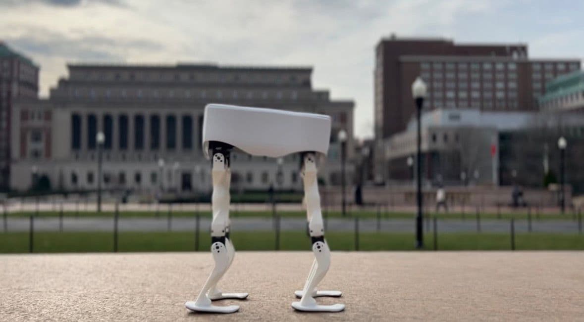
The assembled quadruped walking robot
Top speed
25.6 cm/s
Bus servos
5 daisy-chained
Simulator
MuJoCo digital twin
Control
Raspberry Pi + Telegram

Design · SolidWorks CAD modeling

The mechanical design began with concept sketches evaluating different locomotion approaches before settling on a quadruped configuration for optimal stability and gait versatility. Using SolidWorks I built a complete parametric model of the robot.

  • Four-leg assembly with articulated joints for each leg
  • Servo motor mounting brackets and housings
  • Custom chassis to accommodate electronics and power systems
  • Motion studies to validate range of motion and check for mechanical interference
  • Assembly animations to visualize the walking gaits before physical construction

The CAD model was optimized for 3D printing, with careful attention to print orientation, support material requirements and part tolerances.
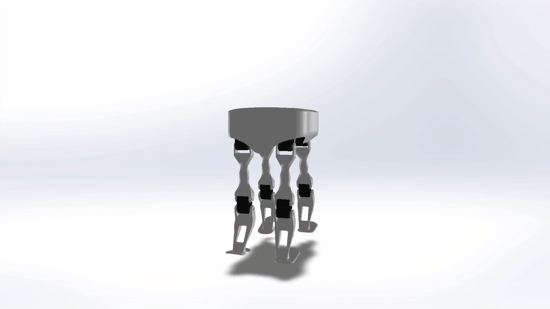
SolidWorks render of the assembled quadruped
The finished assembly rendered in SolidWorks.

Simulation · MuJoCo physics environment

Before committing to physical hardware, I built a custom simulation environment in MuJoCo (Multi-Joint dynamics with Contact) to develop and test walking gaits.

  • An accurate digital twin with matching inertial properties, joint constraints and contact dynamics
  • Sinusoidal gait controllers as a baseline for coordinated leg movement
  • Machine-learning parameter optimization using Random Search and a Parallel Hill Climber to tune phase offsets, stride length and step frequency

Interactive

The digital twin

The geometry as the simulator saw it: the shell left off and the meshes simplified, so the contact solver could run fast enough to optimise against. It walks the trot the hill climber converged on, with the poses baked straight out of MuJoCo.

Fabrication & electronics

3D printing

All structural components were fabricated on Bambu Lab printers.

  • Printed in PLA for ease of use and a sufficient strength-to-weight ratio
  • Post-processing included support removal and light sanding for improved fit
  • Multiple iterations on key components to refine joint clearances and motor mounts

Power system

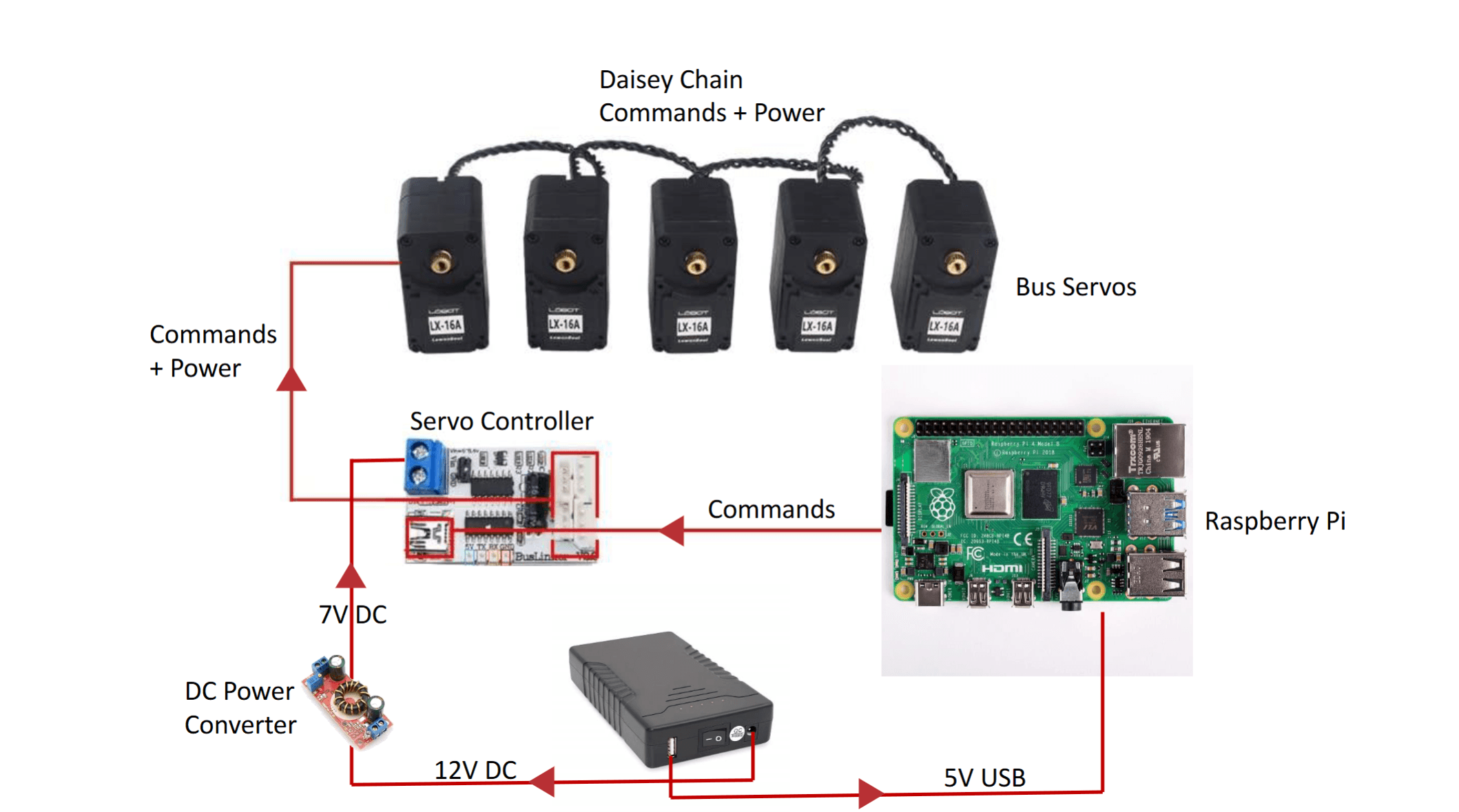
  • 12 V DC external supply as the primary power source
  • DC-DC converter stepping down to 7 V for servo power distribution
  • 5 V USB rail for the Raspberry Pi
  • Daisy-chained power distribution to all bus servos

Control & communication

  • Raspberry Pi as the main control computer, enabling Wi-Fi connectivity and high-level decision making
  • Servo controller board interfacing between Raspberry Pi commands and the servo motors
  • Five bus servos in a daisy chain, individually addressable over a single communication line
  • IMU sensor for real-time orientation feedback and balance control

The architecture lets the Raspberry Pi send high-level motion commands, which the servo controller translates into precise joint angles distributed across the daisy chain.

Electronics architecture: bus servos, servo controller, Raspberry Pi and power rails
The full electrical architecture: 12 V in, stepped down to 7 V for the servo bus and 5 V for the Pi.
The finished build: printed shell over the bus servos and their brackets.

Control interface · Telegram bot

To make the robot accessible and easy to control remotely, I built a Telegram bot interface.

  • Real-time command execution through chat messages
  • Trigger different gait patterns and behaviors remotely
  • Status updates and debugging information sent back to the user
  • Convenient testing and demonstration without physical access to the robot

Reinforcement learning experiments

Beyond scripted gaits, I explored learned control policies.

  • Built a custom Gym environment wrapping the MuJoCo simulation
  • Implemented Proximal Policy Optimization (PPO) for policy training
  • Experimented with several reward formulations for stable forward locomotion
  • The reward tuning never fully converged, but the process was hands-on learning in RL system design, debugging training instabilities and bridging the sim-to-real gap

Lessons learned

  • Sim-to-real transfer is hard: motor backlash, surface friction variability and battery voltage sag all create behavior the simulator does not predict
  • Iteration is essential: multiple design-test-refine cycles were needed for both the mechanical and control systems
  • Systems integration is complex: power distribution, communication protocols, mechanical constraints and control algorithms all constrain each other

The project culminated in a functioning quadruped capable of autonomous walking, with the flexibility to execute different gaits and respond to remote commands.

Next project

Neonatal Incubator with IoT Monitoring